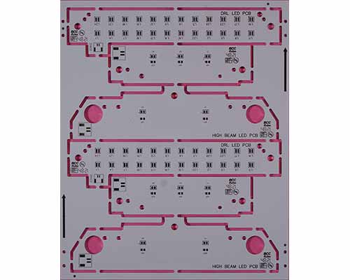
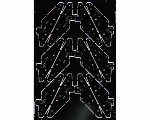
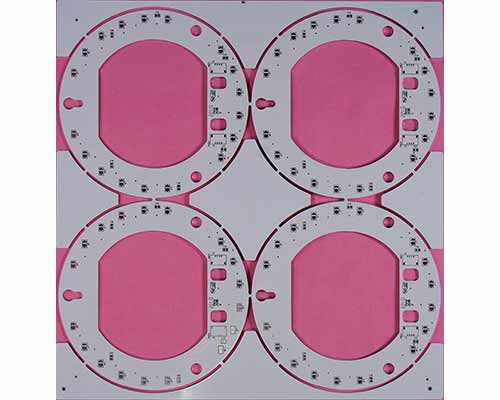
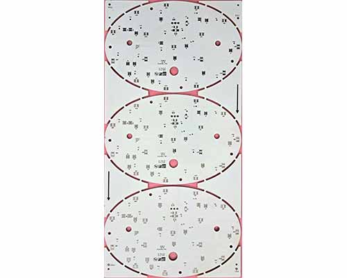
Metal Core Printed Circuit Board (MCPCB) is a type of printed circuit board that has a metal core, typically made of aluminum, copper, or steel, as opposed to the traditional fiberglass core found in most PCBs. The metal core serves as a heat sink, helping to dissipate heat generated by components more effectively than standard PCBs.
Here are some key features and advantages of Metal Core PCBs:
It's important to note that the choice between traditional PCBs and MCPCBs depends on the specific requirements of the electronic application. While MCPCBs excel in thermal management, they might not be necessary for every application, and the increased cost and complexity may not be justified in situations where heat dissipation is not a critical concern.
| Technical Specifications | Standard | Non-standard |
|---|---|---|
| Materials used | FR-4, FR4 (Tg 180) and Metal TG150-core | Ceramin, PTFE |
| Input Media | Gerber Data 274X, Gerber Data D, PCB File, DRL File | Gerber Data 274X, Gerber Data D, PCB File, DRL File |
| Approvals | IATF 16949:2016, UL94 - V0, ISO 9001:2015 | IATF 16949:2016, UL94 - V0, ISO 9001:2015 |
| Copper Thickness | 12 μ to 140 μ | Above 140 μ |
| Board Thickness | 0.30 mm to 3.20 mm | 3.2 mm to 4.5 mm |
| Minimum Hole Size (Finished) | 0.25 mm | 0.20 mm |
| Minimum Line Spacing | 0.15 mm | 0.125 mm |
| Minimum Line Width | 0.15 mm | 0.125 mm |
| Minimum Annular Ring | 0.10 mm | 0.075 mm |
| Maximum Panel Size | 1200 X 508 | 1200 X 508 |
| Minimum Solder Mask Dam | 0.15 mm | 0.10 mm |
| Hole Diameter Tolerence NPTH | +/-0.05 mm | +/-0.05 mm |
| Profile Routing Tolerence | +/-0.20 mm | ,+/-0.10 |
| Aspect ratio | 5.3:1 | 6.4:1 |
| Surface Finish | Lead Free HASL, Tin-lead HASL, and Lacquer | ENIG |
| Solder Mask Colors | Green, Black, White, Red, Yellow, Grey and Blue | All other colours |
| Peelable mask | Top, bottom or both sides | Top, bottom or both sides |
| Electrical test | 100% (Flying probe or fixture test) | 100% (Flying probe or fixture test) |
| Quality Standards | IPC-A-600 J / PERFAG | IPC-A-600 J / PERFAG |